Αναζήτηση

Powered By Blogger

Jan 25, 2018

8-Channel ADC Rpi HAT For Analog-To-Digital Conversions

8-Channel ADC Rpi HAT For Analog-To-Digital Conversions:


Raspberry Pi enthusiasts may be interested in a new 8 channel ADC which has been specifically created for the Raspberry Pi which is capable of providing analog-to-digital conversions.

Created by Chris Burgess the 8-channel ADC for the Raspberry Pi is now available to purchase for $17 or £12.56 directly from the awesome Tindie website.

Chris designed the Raspberry Pi HAT due to the lack of anything currently available in the market when he was building a high powered robot that needed to be able to accurately measure voltages and take analog sensor readings.

Based on the MCP3008 ADC controller IC:

  • 16-pin DIP package.
  • 8-Channel
  •  200 ksps max. sampling rate at VDD = 5V
  •  10-Bits of resolution (when powered with 5V.)
  • Analog inputs programmable as single-ended or pseudo-differential pairs
  • On-chip sample and hold
  • SPI serial interface (modes 0,0 and 1,1)
  • Low power CMOS technology
  • 5 nA typical standby current, 2 µA max.
  • 500 µA max. active current at 5V
  • Industrial temp range: -40°C to +85°C
  • Adafruit Tutorial
Board Features:
8 ADC input Channels:

  • 4-channels configured with voltage divider to allow measuring voltage up to 14.5VDC.
  • 4-channels configured with zero-ohm jumpers to allow for direct-input for ADC measurements.
  • All channels can be reconfigured for zero-ohm jumpers, inline-resistors or in-line capacitors.
  • Channel 0-3 can also be reconfigured for pull-down resistors, or ground-referenced capacitors.
  • 3.3V, 5V, and GND connection terminals.
  • Board can back-power Raspberry Pi via 5V and GND connection terminals.
  • High-quality screw-terminals on all channels.
  • Hardware or Software SPI, selectable via jumpers.
  • SPI can use CEO of CE1, selectable via solder jumper.
  • Footprint for EEPROM and supporting passive components to allow you to turn into true rPI HAT (EEPROM and passives optional.)
  • Stackable header option.


Raspberry Pi compatible Smart Home gateway

Raspberry Pi compatible Smart Home gateway:


The Telegea Smart Hub is designed to be a gateway between the real world and the communication network targeted mainly at IoT applications. It is a custom hardware built around the RaspberryPi Compute Module and therefore compatible with the software from the RaspberryPi ecosystem. It provides a number of standard interfaces for sensors to acquire the data and actuators to control connected devices. Easy to use connectors are provided to ease installation. If needed, functionality can be extended with add-on modules.

The Smart Hub connects to the communication backbone via Ethernet or Wifi (optional) and therefore can provide the data to a cloud service or be controlled remotely.

It is completely user configurable, so different numbers of sensors, actuators or external equipment can be combined with each other. This flexibility allows for many different deployment scenarios which goes from a simple data logging device to a complete smart home solution.

We want to present this new device and share a proof of concept which shows the Smart Home software OpenHAB running on the Telegea Smart Hub hardware.


The dedicated SmartHub OS, the application software and documentation are available from this GitHub repository.


Visit Telegea site

New Arduino IoT Boards Unveiled: MKR WAN 1300 and MKR GSM 1400

New Arduino IoT Boards Unveiled: MKR WAN 1300 and MKR GSM 1400:

At World Maker Faire New York Arduino has unveiled the new Arduino MKR WAN 1300 and the Arduino MKR GSM 1400, two new boards that are designed to offer a practical and cost-effective solution for developers, makers and enterprises.


The new Arduino MKR WAN 1300 is based around the Murata LoRa low-power connectivity module and the Atmel SAM D21 microcontroller, which integrates the 32-bit low-power ARM Cortex-M0+ processor, 256KB Flash memory and 32KB SRAM. The board’s design includes the ability to be powered via either two 1.5V AA or AAA batteries or an external 5V input via the USB interface – with automatic switching between the two power sources.

It also offers the usual rich set of I/O interfaces expected with an Arduino board, and ease of use via the Arduino IDE software environment for code development and programming. Other features of the board include an operating voltage of 3.3V; eight digital I/Os; 12 PWM outputs; and UART, SPI and I2C interfaces.


Like the MKR WAN 1300, the Arduino MKR GSM 1400 is also based on the ARM Cortex-M0+ and the SAM D21 microcontroller, but integrates the u-blox module to deliver global 3G communications ability. The board also features automatic power switching, however, it uses either a 3.7V lithium polymer (LiPo) battery or an external Vin power source delivering 5V to 12V. While the USB port can also be used to supply 5V to the board, the MKR GSM 1400 is able to run with or without the battery connected.

This board also offers a rich set of I/O interfaces including: eight digital I/Os; 12 PWM outputs; UART, SPI and I2C interfaces; analogue I/O including seven inputs and one output; and eight external interrupt pins.

Both of the highly compact boards feature dimensions of only 67.64 x 25mm, together with low power consumption, making them an ideal choice for emerging battery-powered IoT edge devices in the MKR form factor for applications such as environmental monitoring, tracking, agriculture, energy monitoring and home automation.

Learn How to Build a Custom Android App for a ThingSpeak IoT Project

Learn How to Build a Custom Android App for a ThingSpeak IoT Project:

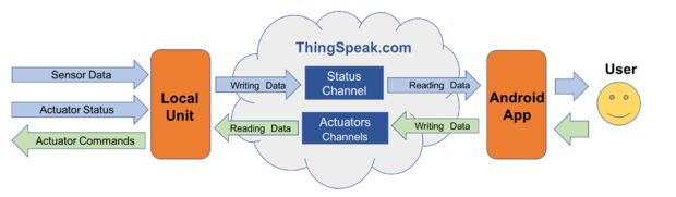
ThingSpeak has APIs for collecting data produced by sensors and APIs for reading that data from applications. Think of an IoT project as two parts. One part of the project is where you need to program a thing to send data. And, the second part is where you want to see that data. ThingSpeak sits in the middle and makes it handy to do both, as Marcelo Rovai points out. Once you have a system like Marcelo’s set up, you can take advantage of integrated online MATLAB Analytics.


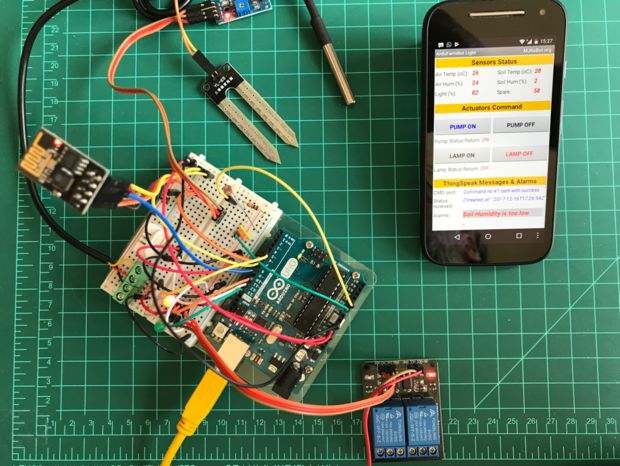
Marcelo has put together a great tutorial that uses ThingSpeak in the middle to collect data from sensors and then display the sensor readings on a custom Android app running on a mobile phone. He uses the MIT App Inventor to create a custom Android app to see the sensor data and status of the system. This project uses easily accessible hardware to build a proof-of-concept IoT system to monitor air temperature, humidity, soil temperature, soil humidity, and luminosity. Other people could modify this project with different sensors or actuators and build something for their own purposes or build a prototype for your next meeting at work.


Check out the full project tutorial on Arduino Project Hub and Instructables. Marcelo provides all of the parts, code, and instructions to make your own prototype IoT system monitored and controlled by a mobile app.

Aug 28, 2016

Shop-built Inspection Camera Lends Optical Help on a Budget

Shop-built Inspection Camera Lends Optical Help on a Budget:

As your builds get smaller and your eyes get older, you might appreciate a little optical assistance around the shop. Stereo microscopes and inspection cameras are great additions to your bench, but often command a steep price. So this DIY PCB inspection microscope might be just the thing if you’re looking to roll your own and save a few bucks.

It’s not fancy, and it’s not particularly complex, but [Saulius]’ build does the job, mainly because he thought the requirements through before starting the build. MDF is used for the stand because it’s dimensionally stable, easy to work, and heavy, which tends to stabilize motion and dampen vibration. The camera itself is an off-the-shelf USB unit with a CS mount that allows a wide range of lenses to be fitted. A $20 eBay macro slider allows for fine positioning, and a ring light stolen from a stereo microscope provides shadow-free lighting.

We’d say the most obvious area for improvement would be a linkage on the arm to keep the plane of the lens parallel to the bench, but even as it is this looks like a solid build with a lot of utility – especially for hackers looking to age in place at the bench.


Filed under: digital cameras hacks, tool hacks


Original enclosures:


ad516503a11cd5ca435acc9bb6523536?s=96

Mar 31, 2016

VoCore: A Cheap And Coin-sized Linux Computer With Wi-Fi

VoCore: A Cheap And Coin-sized Linux Computer With Wi-Fi:


a21aee697d974dc9893d683674ffc5a194390a90_main_hero_image


VoCore is an open source hardware that runs OpenWRT Linux. This tiny computer comes with Wi-Fi, USB, 20+ GPIOs that will help you to embed it on your projects.

With each passing day, mini computer boards are getting more and more popular. Single board computers like Raspberry Pi, CHIP, OrangePi etc. are being endorsed by makers and DIY enthusiasts to create new innovations. However, if you are looking for an even smaller Linux computer, VoCore is the perfect device for you.
VoCore: A Cheap And Coin-sized Linux Computer With Wi-Fi – [Link]

The post VoCore: A Cheap And Coin-sized Linux Computer With Wi-Fi appeared first on Electronics-Lab.

Mar 29, 2016

Start Your Poultry Brood with This DIY Egg Incubator

Start Your Poultry Brood with This DIY Egg Incubator:

You’d think that hatching chicks from eggs would be easy – after all, birds do it. But it turns out to be a fussy business for humans, and what momma bird does naturally isn’t necessarily easy for us. If your goal is to raise your own brood of peeps, fear not – this DIY egg incubator makes the process much easier.

While [Chris Raynerd]’s incubator was built for quail eggs, pretty much any domestic fowl – chickens, turkeys, ducks, pheasants – will work. The key is temperature control – momma bird’s rump is a natural heat source, and her downy feathers keep the eggs insulated and toasty. That’s a little hard to replicate in a free-air incubator, so [Chris] started with a polystyrene box for insulation. A halogen lamp on a digital thermostat provides most of the heat and keeps the temperature within a degree or two of 37°C. As a backup, a 12 volt halogen bulb on a dimmer keeps the chamber at a minimum of 36°, just in case the main lamp burns out. A small fan and a pan for humidifying water complete the atmospheric controls, although personally we’d arrange the fan to blow across the water to aid evaporation. And a simple grid lets [Chris] turn the eggs regularly, which is another vital service mom provides to her brood.

Sure, it could be Arduino-fied and servo driven, but why bother? This is a simple yet thoughtful build that should see a clutch through to hatching. We’ve seen a few egg incubators before, but even if you’re not interested in raising fowl, the techniques here could easily apply to incubators for biohacking or yogurt making, too.


Filed under: misc hacks


Original enclosures:
incubator_featured.png?w=250
ad516503a11cd5ca435acc9bb6523536?s=96

Getting Started With the ATMega328P

Getting Started With the ATMega328P:


F4YN9I5ILWLBJ0D.MEDIUM


Here is a detailed guide on how to get started with ATMega328P microcontroller. The guide goes in details on how to setup it on a breadboard and how to upload your first code on it. and blink a led.

The real benefit of using this microcontroller is that it’s only $4 US, whereas many other micro-controllers are 10X that price. It can also be easily programmed in the universal programming language, C++. The ATMega is also equipped with a decent amount of memory for any project.
Getting Started With the ATMega328P – [Link]

The post Getting Started With the ATMega328P appeared first on Electronics-Lab.

Mar 28, 2016

LiFePO4wered/Pi – LiFePO4 battery for Raspberry Pi

LiFePO4wered/Pi – LiFePO4 battery for Raspberry Pi:


4853551455579281898


Patrick Van Oosterwijck has published a LiFePO4 battery solution for Raspberry Pi that will also act as UPS power supply:

The project is built on top of a LiFePO4wered/USB module. A small board is added with an MSP430G2131 microcontroller that takes care of monitoring input and output voltage, monitoring a PCB touch button, driving a power indicator LED and switching the load (the Raspberry Pi power). The microcontroller is also connected to the Pi’s I2C bus and monitors the Pi’s running state. The small board connects to 8 of the Pi’s GPIO pins but leaves the rest free to allow prototyping using fly leads.
LiFePO4wered/Pi – LiFePO4 battery for Raspberry Pi – [Link]

The post LiFePO4wered/Pi – LiFePO4 battery for Raspberry Pi appeared first on Electronics-Lab.

Mar 25, 2016

Hacking The Raspberry Pi WiFi Antenna For More dB

Hacking The Raspberry Pi WiFi Antenna For More dB:

I’ve been testing out the Raspberry Pi 3, and one thing I have found is that the WiFi antenna that was added in this new model is not especially good: the Pi has trouble connecting to my WiFi network in places that other devices have no issues. That’s not surprising, because the antenna on the Pi 3 is tiny: mounted right next to the display connector, it is just a few millimeters wide. [Ward] at DorkbotPDX agrees, so he decided to look into adding a better antenna by adding an external connector.

He tried two approaches: replacing the antenna with a tail connector, and adding a U.FL connector to the unused solder pads on the board. Both require some delicate soldering work, so they aren’t approached lightly. Replacing the antenna with an external connector produced a significant increase in signal output, which should equate with more range for the WiFi connection.

It is also interesting to note that the Pi 3 has solder pads on the board to add an external antenna connector, but that they are not used. Plus, one of the solder pads is covered by solder mask. Using these is the second approach that [Ward] used, soldering on a U.FL connector and connecting that to a small rubber duckie antenna. Again, this proved more efficient, increasing the power output of the antenna significantly.

NOTE: This hack definitely falls into “Don’t try this at home” territory. Messing with antennas voids the warranty and FCC certification for the Pi, and can cause all sorts of signal-related unpleasantness if you aren’t careful.


Filed under: Raspberry Pi


Original enclosures:
top_rotated_featured.png?w=250
ad516503a11cd5ca435acc9bb6523536?s=96

Internet-of-Things Power Meter

Internet-of-Things Power Meter:


9546711451470984238


This is a simple, cheap, easy to build IoT Power Meter that provides accurate statistics on household power consumption:

The Internet-of-Things Power Meter (IPM) is a device fixed on top of the regular household power meter that provides detailed information about the electricity usage. Modern power meters have a LED blinking every time a Watt is used, the IPM detects these flashes using a light sensor, counts them, saves the values to an SD card. Later the data is stored to the cloud.
Internet-of-Things Power Meter – [Link]

The post Internet-of-Things Power Meter appeared first on Electronics-Lab.

Improved Arduino Rotary Encoder Reading

Improved Arduino Rotary Encoder Reading:


F3C2AUIIM28ZIL3.MEDIUM


Here is a nice tutorial on how to use rotary encoders with Arduino. Example code is included.

I wanted to use a low cost rotary encoder as an input mechanism for one of my upcoming projects and was initially bewildered by the code options available to take readings from the rotary encoder and determine how many “detents” or cycles the encoder had clicked past and in what direction.
Improved Arduino Rotary Encoder Reading – [Link]

The post Improved Arduino Rotary Encoder Reading appeared first on Electronics-Lab.

Mar 15, 2016

Setting up ESP8266 based DS18B20 sensor temperature monitoring with Emoncms

Setting up ESP8266 based DS18B20 sensor temperature monitoring with Emoncms

http://www.instructables.com/id/Esp8266-Sensor-Temperarture-DS18B20-to-Emoncms/

If you are looking for ways of measuring and logging temperature data online, then you can try this one. Jhon_Control describes his setup in this instructable where uses ESP8266 module as microcontroller platform where DS18B20 probe is attached. As you may already know, ESP8266 has two programmable GPIO where one was used for reading temperature using 1-wire protocol.


The temperature data is sent via wireless interface, but additionally it can be read via serial interface where other debugging information is present. The other part of project is where temperature data goes. He has chosen OpenEnergyMonitor (Emoncms) – the web platform which can be freely installed on your local host computer and even Raspberry Pi. Here you can have nice representation of data including graphs, history, calculations, and other fancy stuff. You can start with single sensor, then expand to multiple and even join data from different sources and locations.

Mar 11, 2016

5A Adjustable Regulated Power Supply

5A Adjustable Regulated Power Supply:


5A_Adjustable_Regulated_Power_Supply_G006


This project provides a variable output voltage ranging from 1.2 to 32 V @ 5 A. Project based on LM338K IC, LM338K is adjustable 3 terminal positive voltage regulator capable of supply in excess of 5A over a 1.2V to 32V output range, simple circuit consist few components.

Features

  • Input Supply : 24 VAC or 30 VDC, 5 Amp
  • Output : variable output from 1.2 to 32 V @ 5 A regulated low ripple DC voltage
  • Heatsink for regulator IC
  • Onboard bridge rectifier to convert AC to DC
  • LED indication at input of IC
  • Thermal overload/short circuit protection (provided by IC feature)
5A Adjustable Regulated Power Supply – [Link]

The post 5A Adjustable Regulated Power Supply appeared first on Electronics-Lab.

How to Implement Embedded Ethernet

How to Implement Embedded Ethernet:


sku_166604_1


Maurizio @ dev.emcelettronica.com has tipped us with his latest article on how to implement embedded Ethernet on any mcu. The article shows the basic principle of Ethernet implementation.

Usually We need embedded systems inside devices, particularly the so-called intelligent devices, to communicate with a command/control/administrative center. Typical such situations could be a remote security camera that can send you video clips when queried, an embedded system that can send status when checked through a web browser or a vending machine that is capable of sending an email when service is required.
How to Implement Embedded Ethernet – [Link]

The post How to Implement Embedded Ethernet appeared first on Electronics-Lab.