Αναζήτηση

Powered By Blogger

Jan 16, 2016

Using a $2 DS3231 RTC & AT24C32 EEprom from eBay

Using a $2 DS3231 RTC & AT24C32 EEprom from eBay:


cheaprtc


From the comments on our ‘Using DS1307 and DS3231 real-time clock modules with Arduino‘ post, Edward Mallon writes:

I’ve been putting the $1 DS3231 boards through their paces for quite a while now…and they have been performing well.
More details at Edward Mallon’s blog.

Via the comments.

Make your own open hardware guitar amplifier

Make your own open hardware guitar amplifier:


ElectroSmash just released an open hardware guitar amplifier called the 1Wamp. Designed as a small and portable 1 watt amplifier loaded with all the features of big amps, the project was fully developed using only open source tools—like KiCAD, a design suite to create schematics and layouts in any platform.

We published a detailed analysis of each part of the amplifier so that anyone can contribute to improving or modifying it, as well as, sharing their thoughts and work on the 1Wamp forum.

The amplifier features:

  • Tone/Volume/Gain controls
  • Speaker/Cabinet output
  • Headphones output with attenuator switch
  • Aux/mp3 input
  • 9V battery clip
  • 9V DC boss style power input jack

How to build 1Wamp in 5 steps

Here’s a summarized version from our full documentation.

Step 0

You will need a soldering iron, lead, and cutting pliers. You can get the PCB from ElectroSmash, or build your own at home using the native files or PCB layout transfers from the forum.


1wamp-start-big.jpg
 Photo by Ray Rodriguez, CC BY-SA 4.0

Steps 1, 2, 3, and 4

Soldering the components to the PCB is easy; just follow the Bill of Materials and solder the parts, beginning with the small ones. Then put the larger components in place.

Some tips:

  1. Pay attention to diodes polarity, there’s a line indicating the correct position.
  2. Be careful with the electrolytic caps polarity, the negative lead (the short one) has to be placed in the round hole. The positive hole is always square-shaped and it is marked with a “+” symbol.
  3. Be patient soldering the big components perpendicularly, because they tend to be slightly tilted.

Step 5

It’s time to check your work. Double-check your PCB with the model, component by component, before powering it up. Use this checklist:

  • Visual inspection of the PCB bottom, there is no short circuits or long uncut leads.
  • The polarized components are placed correctly: diodes and electrolytic caps.
The circuit board fits into several enclosures (like the Hammond 1590B and 1591C), and the plastic cover can also be used as lighting plate.
files and schematics here: Make your own open hardware guitar amplifier

Inject Packets with an ESP8266

Inject Packets with an ESP8266:

[Kripthor] sent us a link to his blog where he writes the Hello World of low-level networking. Basically he’s constructing his own packet and sending it. By itself this isn’t a bad thing. You could use this power for all sorts of networks-diagnostic good. And so, despite the ominous name of his blog post “ESP8266 Jamming”, he’s not really doing anything that bad — he’s just creating many fake WiFi beacon frames and sending them out every so often.

Which can apparently do bad things to some vulnerable routers. Who knew? Want to test yours?

Naturally we wanted to see how he was doing it, and we opened up the Arduino code in GitHub. It turns out that Espressif has written a wifi_send_pkt_freedom() function that just sends out whatever packet you’d like to the network. That was easy.

It also turns out that the ESP8266 will enter monitor mode, where it listens to all WiFi traffic regardless of the MAC address that it’s directed toward. [Pulkin] seems to have done the work for us and posted the code in his GitHub. Now things get nasty. Combining promiscuous monitor mode with some carefully constructed management frames can end up with a classic WiFi deauth denial-of-service attack on a $2 piece of hardware.

We think it’s tremendously cool that the ESP8266 packs such power, and we beg you all to use it responsibly. The last thing we want to see is the world littered with WiFi-DOS throwies. And the last thing you’d want is a visit from the FCC.

Raspberry Pi Wind Measurement

Raspberry Pi Wind Measurement:

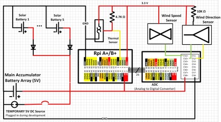
A well organized approach to a project is a delight to see. [Pavel Gesyuk] takes just that approach with the experiments on his blog. Experiment 13 is a multi-part series using a Raspberry Pi as the heart of a weather station. [Pavel] is looking at wind speed and direction, and temperature measurement, plus solar power for the station. One of his videos, there are many, is after the break.


electrical_02_t
The anemometer and direction sensors are stock units wired to a Raspberry Pi A+ using an analog to digital daughter board. The data from the temperature sensor is acquired using I2C. During one part of the experiment he uses an EDIMAX WiFi adapter for collecting the data.

Python is [Pavel’s’ language of choice for development and freely shares his code for others to see. The code collects the data and displays it on a monitor connected to the Pi. The experiment also attempts to use solar power to charge batteries so the station is not dependent on mains power.

The mechanical assembly shows attention to detail commensurate with his project presentation and we respect how well organized the work is.


Filed under: Raspberry Pi, software hacks, solar hacks


Original enclosures:
feature.jpg?w=150
ad516503a11cd5ca435acc9bb6523536?s=96
electrical_02_t.jpg

Jan 14, 2016

Arduino 5 Minute Tutorials – Lesson 9 – Programming Arduino Platforms Using a Different IDE

Arduino 5 Minute Tutorials – Lesson 9 – Programming Arduino Platforms Using a Different IDE:

banner_arduino_tutorial_lesson_9


Lessons Menu:

So, you’ve installed the Arduino IDE and used it for a little while but now you are looking for something different. Maybe it wasn’t quite what you expected, it is too complicated, simple or something else that doesn’t meet your requirements. Well, there is hope! In this article we present to you other software options for programming your Arduino platform with. In this list of alternatives, we decided to split them into two major categories: visual programming and regular programming.


Since this is only a short list of possible tools to program your favorite Arduino platform with, please let us know in the comments what you use (and why!) or any other thoughts on the options proposed here or others that we haven’t listed.


software_0_arduino


Arduino IDE 1.6.7

Visual Programming

These alternatives provide the user with the ability to create programs graphically instead of writing code (text).

Regular Programming

These allow you to code as normal (text), but provide a different interface and features to help improve your experience by facilitating some advanced tasks usually not possible with the Arduino IDE.

ArduBlock

While this one has not been updated in a little while, it is still a nice interface and can help you learn Arduino programming using blocks. You can download from sourceforge directly here. The main website seems to be down recently but you can see the Getting Started guide using a backup from archive.org for now.


software_1_ardublock


Ardublock

BlocklyDuino

This is a web-based visual programming editor. It is based on Blockly.


You can see a demo here and get the source code here to install it locally.


software_2_blocklyduino


BlocklyDuino

miniBloq

Like ArduBlock, this software allows for visual programming Arduino platforms using blocks. You can download it here. We recommend that you also read the documentation.


miniBloq


miniBloq

Modkit Micro

Another block based programming interface with slight differences. This one can both run locally or through a web browser.


You can download it here or access it online directly here.


software_4_modkit


Modkit Micro

Scratch for Arduino (S4A)

S4A is a Scratch modification that allows for simple programming of the Arduino platform.


You can find the steps to download & install it here. This one also offers Android communication.


software_5_s4a


S4A

Atmel Studio

Atmel is the manufacturer of the AVR chips used in making most Arduino (and Arduino-compatible) microcontroller boards. If you wish to create more complex projects, this software can certainly help with debugging and many other features. With recent versions, it also allows “one-click import” of Arduino projects. You can learn more about it here.


software_6_atmelstudio


Atmel Studio

CodeBender

This option offers a web-based IDE where all your software is stored on the cloud. It also allows users to easily share software and collaborate with each other. You can check it out here. There is also an interactive demo showing the basics.


software_7_codebender


CodeBender

Eclipse

Eclipse is a well-known, open source and full-featured development environment that can be set up to work with AVR and Arduino by using a plug-in and some extra configuration. You can learn more about how to install it on the Arduino Playground.


software_8_eclipse_2


Eclipse


Jan 13, 2016

Color Identifier with Python and OpenCV

Color Identifier with Python and OpenCV:


OpenCV Logo
A while back a friend of mine asked me to help him build an app that used computer vision to detect things like traffic lights & road signs. The idea was to use his Raspberry Pi and Pi Cam as a dashcam in his car. He wanted it to identify traffic lights that were red and play some sort of sound letting him know the light was red and that he needed to stop. Once the light turned green, it would play another sound letting him know that he could proceed. He also wanted to have the app do several other things, all of which were based off of color. Normally I would recommend using something such as a Haar classifier or dedicated algorithm for detecting such objects. But, I also wanted to see for myself whether it would be possible to detect objects based entirely on their color. The results were actually very good and the speed of the app outperformed some of the best algorithms available.

In order for me to know the RGB values of the objects he wanted to detect, I wrote a simple tool that uses Python and OpenCV to filter out all colors except the colors I am interested in, leaving me with the RGB values I needed to plug into the app. Now, I know that there are plenty of tools out there that can be used to identify RGB values of objects in images. But, being the geek that I am, I opted to write my own tool. Plus, this was just another opportunity for me to do some work with computer vision. Since I enjoyed playing around with this tool and found it helpful for my friend’s dashcam project, I thought I would share the app in case anyone else might also find it useful / fun.

Aside from Python, the only thing you need is the OpenCV library compiled for Python. If you don’t have it, don’t worry. I’ve included it in the ZIP linked to at the end of this post. You will also need some images to play with. Since one of the objects my friend wanted to detect was a red traffic light, I have also included 3 images in the ZIP that contain scenes from intersections. Here is the image I used as a demo when writing this post.


traffic_light2


You can swap out my images with whatever images you want by simply replacing the image_filename at the beginning of the code with the path to your image of choice. Once you’ve done that, run the Python app. The app will launch a window that contains slider bars at the top and your image at the bottom. Simply adjust the sliders at the top of the app and you will see colors get filtered from your image. Here are a couple of screenshots of my demo while adjusting the sliders.


outlines_half


outlines


If you keep adjusting the sliders, you will eventually end up with the RGB values for only the color you are looking for as shown in this final result from filtering out everything except the red traffic lights.


red_lights_only


As you can see in the source code below, I have already hardcoded the best values for each of the test images included in the ZIP. When you run the app, the sliders will default to these values (assuming you have uncommented the values for the image you are using). Feel free to modify these values (or the rest of the code) to fit your needs. Enjoy!

import cv2.cv as cv

image_filename = 'images/traffic_light2.jpg'

#traffic_light1.jpg
#mR_val = 254
#mG_val = 105
#mB_val = 0
#MAR_val = 256
#MAG_val = 138
#MAB_val = 17

#traffic_light2.jpg
mR_val = 172
mG_val = 136
mB_val = 150
MAR_val = 256
MAG_val = 256
MAB_val = 256

#traffic_light3.jpg
#mR_val = 144
#mG_val = 100
#mB_val = 134
#MAR_val = 256
#MAG_val = 256
#MAB_val = 205

def set_RGB(pos):
    mR_val = cv.GetTrackbarPos('minR', winName)
    mG_val = cv.GetTrackbarPos('minG', winName)
    mB_val = cv.GetTrackbarPos('minB', winName)

    MAR_val = cv.GetTrackbarPos('maxR', winName)
    MAG_val = cv.GetTrackbarPos('maxG', winName)
    MAB_val = cv.GetTrackbarPos('maxB', winName)
    
    min_color = cv.CV_RGB(mR_val, mG_val, mB_val)
    max_color = cv.CV_RGB(MAR_val, MAG_val, MAB_val)
    cv.InRangeS(hsv, min_color, max_color, mask)
    cv.ShowImage(winName, mask)

# setup window
winName = 'Color Identifier'
cv.NamedWindow(winName, cv.CV_WINDOW_AUTOSIZE)

min_color = cv.CV_RGB(mR_val, mG_val, mB_val)
max_color = cv.CV_RGB(MAR_val, MAG_val, MAB_val)

cv.CreateTrackbar('minR', winName, mR_val, 256, set_RGB)
cv.CreateTrackbar('minG', winName, mG_val, 256, set_RGB)
cv.CreateTrackbar('minB', winName, mB_val, 256, set_RGB)

cv.CreateTrackbar('maxR', winName, MAR_val, 256, set_RGB)
cv.CreateTrackbar('maxG', winName, MAG_val, 256, set_RGB)
cv.CreateTrackbar('maxB', winName, MAB_val, 256, set_RGB)

img = cv.LoadImage(image_filename)
hsv = cv.CreateImage(cv.GetSize(img), 8, 3)
cv.CvtColor(img, hsv, cv.CV_BGR2HSV)
mask = cv.CreateImage(cv.GetSize(img), 8, 1)
cv.Zero(mask)

cv.InRangeS(hsv, min_color, max_color, mask)

# show image
cv.ShowImage(winName, mask)
cv.WaitKey(0)
cv.DestroyWindow(winName)
Download: Python source code, OpenCV library, and test images. (5.5MB ZIP)

The post Color Identifier with Python and OpenCV appeared first on Prodigy Productions, LLC.

Arduino ProtoShield

Arduino ProtoShield:

FU4B4KFIJAAAIX7.SMALL.jpg
In this project, we will be making an Arduino Protoshield which supports and electrically connects electronics components to the Arduino for better wiring and design.It’s a fairly easy project and could be used on variety projects. List of Material For this project, we will be using:- Arduino boa...

By: AdrieSentosa


Continue Reading »


Low Cost Foundry/forge

Low Cost Foundry/forge:

FGK1LLEII7PH5VD.SMALL.jpg
This is my design for a metal melting foundry that also works as a forge. Materials needed: 1 old beat up standard propane tank Portland cement Silica sand Wood ashPerlite (not vermiculite) Fireclay External parts:Forge burner------ I used the burner from this instructablehttp://www.instructables.co...

By: chaotech creations


Continue Reading »


Zip Tie Stand-offs

Zip Tie Stand-offs:

FM2VGFHIJBTVZU6.SMALL.jpg
What I want to share with you is a little trick I discovered for tidying up wires, brake lines, cables ect. along frame rails, cross members, or anywhere you would be running such stuff. I've used this technique on motorcycles for running hard brake lines along side frame sections with great results...

By: mech4fun


Continue Reading »


Jan 12, 2016

Guide to ESP8266 and Tweeting Using ESP8266

Guide to ESP8266 and Tweeting Using ESP8266:


FONIOTZIJ5TYSJH.MEDIUM


Subhan95 @ instructables.com has written a tutorial on how to use ESP8266 with Arduino and tweet using it.

What can the ESP8266 do?It is limited by your imagination.I have seen projects and tutorials on the internet showing how to fetch a city’s temperature, stock prices,sending and receiving emails ,making phone calls and much much more.I will show in this Instructable how to send a tweet.
Guide to ESP8266 and Tweeting Using ESP8266 – [Link]

The post Guide to ESP8266 and Tweeting Using ESP8266 appeared first on Electronics-Lab.

Jan 11, 2016

SerialUSB: A cheap USB proxy for input devices

SerialUSB: A cheap USB proxy for input devices:


687474703a2f2f67696d782e66722f696d672f73657269616c7573622f73657269616c7573622d6370323130322d776972696e672d732e706e67


Serialusb is a cheap (~$5) USB proxy intended to be used with input devices. It is the combination of:

  • a PC software operating the host side of the proxy
  • an atmega32u4 firmware operating the device side of the proxy
SerialUSB: A cheap USB proxy for input devices – [Link]

The post SerialUSB: A cheap USB proxy for input devices appeared first on Electronics-Lab.

chipKIT Tutorial: Using Nokia 5110 LCD

chipKIT Tutorial: Using Nokia 5110 LCD:


T7_Title-580x447


Raj @ embedded-lab.com has posted another great tutorial on how to interface a Nokia 5110 LCD to chipKIT board.

Today, we will see how to connect a NOKIA 5110 graphical LCD (used in Nokia 5110 cell phones), which is a 84×48 pixel monochrome display of about 1.5″ diagonal in size. The display can be used for graphics, text, and bitmaps.
chipKIT Tutorial: Using Nokia 5110 LCD – [Link]

The post chipKIT Tutorial: Using Nokia 5110 LCD appeared first on Electronics-Lab.

Jan 9, 2016

5V from Portable Wind Turbine

5V from Portable Wind Turbine 

5V from Portable Wind Turbine 

T.K. Hareendran

This project deals with the design and development of a portable wind turbine unit, capable of generating electricity from the kinetic energy in the wind. The circuit requires a DC motor, fan blades or propeller, DC-DC boost converter and wind energy to produce a 5V DC output.

Wind-power generation is a fairly simple process that uses an ordinary miniature DC motor to make a very simple wind turbine generator. A miniature DC motor, like RF-300FA-12350, is easily available in the market but can also be taken out from an old CD/DVD drive/player (refer Fig. 1).

Fig. 1: Miniature DC motor

Fig. 2: Wind turbine blades/propeller 

Fig. 3: DC-DC boost converter
  
  Fig. 4: Circuit diagram for deriving 5V from the
  portable wind turbine
A small propeller, or fan blades, can be mounted directly onto the motor shaft. Note that the electricity generated by the motor is DC, and hence no AC-DC conversion circuitry is required apart from a polarity guard diode. In fact, the polarity guard diode is also not required since the propeller rotates in only one direction (counter-clockwise) in this model, due to the unique design structure of the plastic wind turbine blades/propeller.

Compact and light-weight plastic fan blades/propellers are available. A generic three-leg plastic propeller (shown in Fig. 2) is used in this project.

Jan 1, 2016

INA219 current sensor DIY Breakout board

INA219 current sensor DIY Breakout board:


23577455661_4c48a0beca_z


A INA219 current sensor DIY Breakout board project from Juan Ignacio:

Another small board, this time for a INA219. The INA219 is a high-side current shunt and power monitor with an I2C interface.

For testing I used Rei VILO library with a MSP430G2553 and Energia, and I measured the power consumption for this simple circuit.
Project info at ssihla homepage.

Reverse engineering the ESP8266 WIFI-to-Serial port adapter

Reverse engineering the ESP8266 WIFI-to-Serial port adapter:


Here’s a video from electronupdate on reverse engineering the ESP8266 WIFI-to-Serial port adapter:

Another very interesting bit of technology. The combination of so much functionality into such a small part is a real touch-stone as to where things are heading.

A quick look at the antenna design to see if I could sort down the details and then some die-decap to analyze the silicon a bit. The RF section is especially interesting. In the video I call out a section as being an inductor… on second thought as I type this it might even be a transformer?

Amazing…
More details at electronupdate blog.