DYI INLINE FILTER, PC Water Cooling:
For Computer water cooling there's not a lot of options forinline filters that offer capacity and high flow.This Kurig "MY K Cup" seemed to me like a perfect solution and was basically only lacking a set of G1/4 fittings. and since my Kurig 1.0 died and the new 2.0 dosn't work with these, don't get ...
By: MattZilla_82
Continue Reading »

Oct 31, 2015

Sensor Technology for Health and Fitness Applications
Sensor Technology for Health and Fitness Applications:
By Jon Gabay @ digikey.com:
The post Sensor Technology for Health and Fitness Applications appeared first on Electronics-Lab.
By Jon Gabay @ digikey.com:
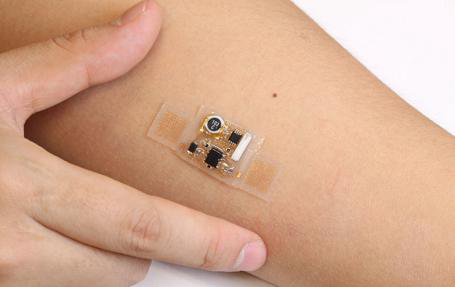
Determining the state of our health has always been a matter of finding a way to monitor and measure the body’s most basic functions. Before instrumentation, visual indicators were used that allowed us to know, for example, what our body temperature should be, what a healthy pulse is, and what an acceptable respiration rate is.Sensor Technology for Health and Fitness Applications – [Link]
Today, with an aging population more people now need some sort of portable health monitoring, which could take the form of devices that, among other things, dispense medication at regular intervals, stimulate the heart, or measure blood sugar levels and inject insulin. This article looks at medical- and fitness-sensor technology—contacted and contact-less, placed on the skin, subcutaneous, or internal—that now or soon will be available to design engineers. All parts, tools, and data referenced here can be found on the Digi-Key website.
The post Sensor Technology for Health and Fitness Applications appeared first on Electronics-Lab.
Oct 28, 2015
Portable GPS Data Logger
Portable GPS Data Logger:
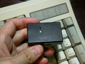
elm-chan.org has build a portable GPS logger based on ATMega328 mcu:
The post Portable GPS Data Logger appeared first on Electronics-Lab.
elm-chan.org has build a portable GPS logger based on ATMega328 mcu:
I have built a GPS Logger and it works very well to trace the drove route for two years. By the way, the navigation solution computed by GPS receiver itself has an excellent accuracy without DGPS because an intentional offset added by US goverment has been stopped several years ago. The position error seems to be some meters under clear sky. It is a suffcient accuracy to trace the movement of walk. However that GPS logger was designed for only car use so that I re-designed a portable one.Portable GPS Data Logger – [Link]
The post Portable GPS Data Logger appeared first on Electronics-Lab.
A Small, 1000W Induction Heater
A Small, 1000W Induction Heater:
[Proto G] built a small, desktop induction heater that is capable of making small castings, melting small amounts of metal, and functioning as one of the best solder pots we’ve ever seen.
The induction heater is built from a custom Zero Voltage Switching (ZVS) driver and powered by a small 48V, 1000W power supply. While this makes for an exceptionally small induction heater, it’s still very capable. In the video below, it only takes a few seconds to heat a screwdriver up to a temperature that will melt solder.
While an induction heating machine is essentially useless for irons unless you have a few antique, unpowered, blowtorch-powered soldering irons, it does make for a great solder pot. [Proto G] replaced the working coil in his induction heater with litz wire. The actual solder pot is made out of steel conduit wrapped with aerogel-infused fiberglass insulation. Compared to his old solder pot, this machine heats up instantly, and is more than capable of wetting a few wire connections.
The future plan for this inductive heater is to make a few more attachments for different metals, and a [Proto G] has a few aerogel blankets he could use to make some small metal castings.
Filed under: tool hacks
| Original enclosures: |
| zvs.png?w=150 |
| ad516503a11cd5ca435acc9bb6523536?s=96 |
El Cheapo Electric Screwdriver
El Cheapo Electric Screwdriver:
If you have a few hobby servos lying around, here’s a hack that let’s you recycle them and put them to good use. [Kedar Nimbalkar] took a micro servo and converted it into an electric screwdriver. It is simple enough to deserve a short video showing how he did it.
He starts by opening up a 9G micro servo and removing the electronics. All that’s needed is the DC motor and the gears. The two motor wires go directly to the battery via a polarity reversal switch to allow the motor to turn in both directions. The servo horn is cut to size so that it is a tight fit inside the screwdriver socket. A liberal amount of glue is used to make sure it stays in place. The horn is then attached to the modified servo, ready to take interchangeable bits. One last mod before closing up the servo is to convert it to continuous rotation by cutting off the stopper in the drive gear.
He built the power supply from scratch, using a 18650 Li-Po battery, a 5V USB charger, a DPDT switch to allow direction control and a push button to actuate the screw driver. A pair of LED’s connected back to back serve as direction indicators as well as some local illumination.
There’s lot’s of scope to improvise and do everything differently, but the basic premise of using unused servos for a handy electric screwdriver is pretty neat.
Filed under: tool hacks
| Original enclosures: |
| screwdriver01.png?w=150 |
| ad516503a11cd5ca435acc9bb6523536?s=96 |
Oct 27, 2015
Pixy camera: detect the colour of the objects and track their position
Pixy camera: detect the colour of the objects and track their position:
By Boris Landoni @ open-electronics.org:
The post Pixy camera: detect the colour of the objects and track their position appeared first on Electronics-Lab.
By Boris Landoni @ open-electronics.org:
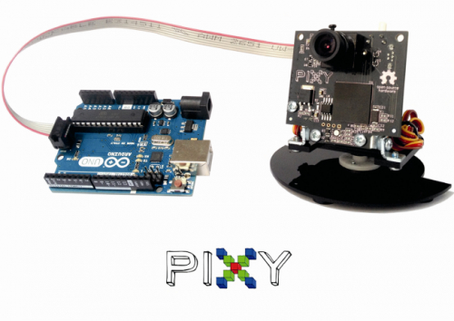
Here we present our first tests with the Pixy camera, a device capable of detecting the colour of the objects, and to track their position.Pixy camera: detect the colour of the objects and track their position – [Link]
Until a short time ago, it was really difficult to develop applications able to take advantage of artificial vision algorithms, and most of all by using systems with limited hardware resources.
Luckily, however, things have changed now: in addition to the various open source frameworks that help developers to easily implement even the most complex algorithms, complete peripherals are spreading, be it for the hardware part (providing the acquisition of images coming from the outside world), or for the software part (able to analyze and read such images). With such peripherals it is possible to create applications provided with artificial vision, in a really simple way.
The post Pixy camera: detect the colour of the objects and track their position appeared first on Electronics-Lab.
DIY Capacitance Meter
DIY Capacitance Meter:
electro-labs.com published another great project based on Atmega328P:
The post DIY Capacitance Meter appeared first on Electronics-Lab.
electro-labs.com published another great project based on Atmega328P:
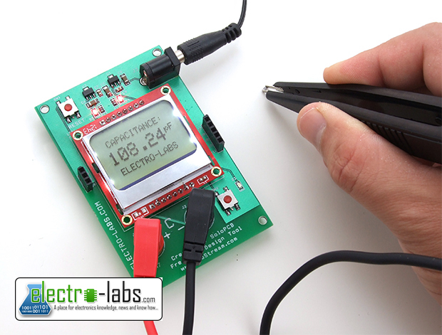
We are building another opensource SoloPCB project which is very enjoyable to build and use. In our electronics works, we frequently need to know the actual value of a capacitor. As you know, small sized SMD capacitors have no markings showing their values. Or there are lots of fake electrolytic capacitors which are rated much lower than their stated values. Sometimes the capacitors have large tolerances and we want to choose the best fit for our circuit. What we need is an accurate capacitance meter.DIY Capacitance Meter – [Link]
This is a capacitance meter which can measure capacitors rated from picofarads to millifarads. The principle of operation is simple. Just apply voltage to the capacitor and measure the elapsed time to charge it. The circuit is based on Atmega328P and it is Arduino IDE compatible. It includes the voltage regulators which output 5V and 3.3V from 9V input. A Nokia 5110 LCD is used to display the measured information. Thanks to the 4mm banana jacks, various kinds of probes can be used such as SMD probe, crocodile probe etc.
The post DIY Capacitance Meter appeared first on Electronics-Lab.
Arduino with GSM and PIR Sensor
Arduino with GSM and PIR Sensor:
by motheeb @ instructables.com:
The post Arduino with GSM and PIR Sensor appeared first on Electronics-Lab.
by motheeb @ instructables.com:
This lesson will allow you to use SMS to control an LED along with using Arduino to make automatic calls to your phone in case it sensed movements in your room. You will be able to listen to the voices there and act upon emergency.Arduino with GSM and PIR Sensor – [Link]
The post Arduino with GSM and PIR Sensor appeared first on Electronics-Lab.
Attiny85 EMF detector
Attiny85 EMF detector:
by masteruan @ instructables.com:
The post Attiny85 EMF detector appeared first on Electronics-Lab.
by masteruan @ instructables.com:
This is a simple tutorial to create an EMF detector. You can use Arduino for this job, but is better use a microcontroller called Attiny85. It is possible program it throe the Arduino interface.Attiny85 EMF detector – [Link]
The post Attiny85 EMF detector appeared first on Electronics-Lab.
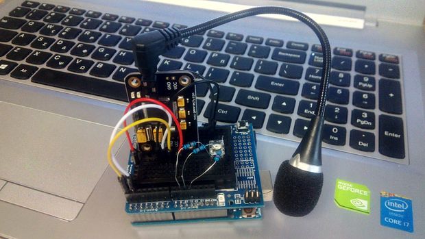
How to use a Serial Voice Recognition Module
How to use a Serial Voice Recognition Module:
by codebender_cc @ instructables.com:
The post How to use a Serial Voice Recognition Module appeared first on Electronics-Lab.
by codebender_cc @ instructables.com:
In this tutorial you will learn how to use a voice recognition – serial – module with the Arduino uno board. This module can store up to 15 voice commands. Those are divided into 3 groups, with 5 commands in each group.How to use a Serial Voice Recognition Module – [Link]
First we should train the module with voice instructions group by group. After that, we should import one group before it could recognize the 5 voice instructions within that group.If we need to implement instructions in other groups, we should import the group first. Only one group can be active per time.
In this tutorial we will use an RGB LED and we will try to change the color of it with voice commands.
The post How to use a Serial Voice Recognition Module appeared first on Electronics-Lab.
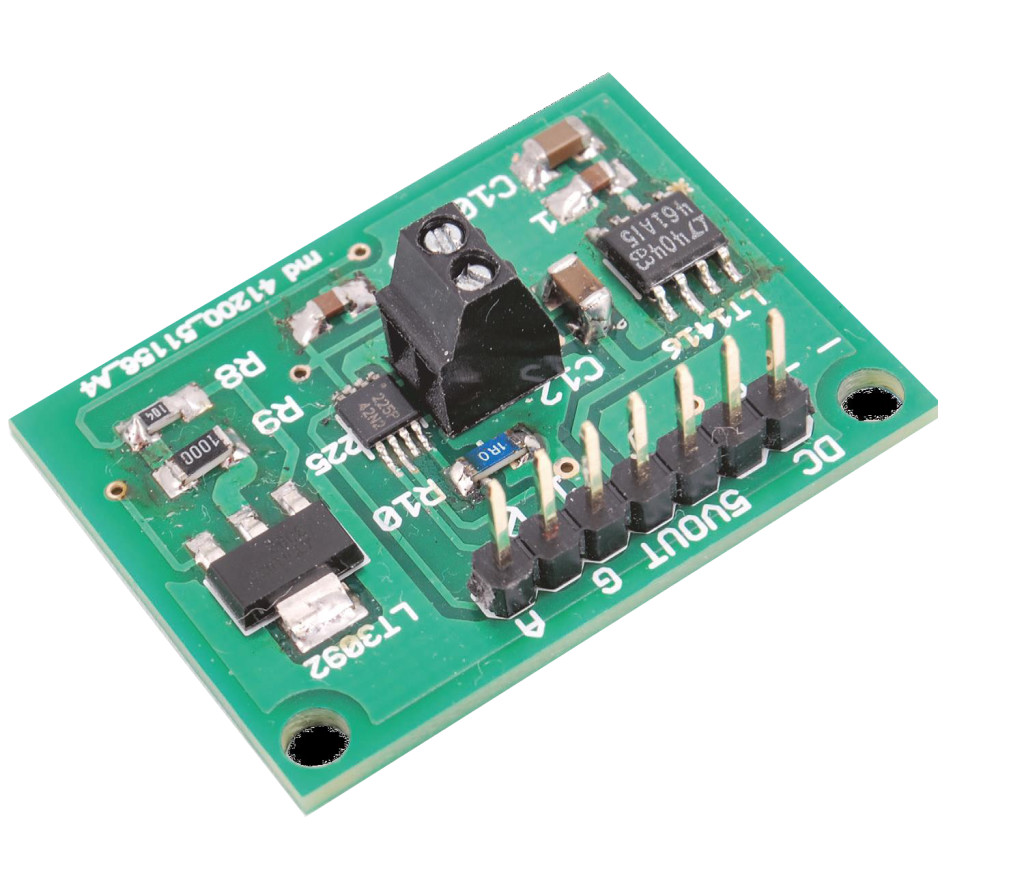
DIY milliohmmeter
DIY milliohmmeter:
by hwmakers.eu:
The post DIY milliohmmeter appeared first on Electronics-Lab.
by hwmakers.eu:
This is an example of a simple and cheap milliohmmeter that can be made by every maker. The core of the circuit are a current source (LT3092) and a current sense (INA225): a costant current flows through the milliohm resistor under test and the voltage at the current sense output gives the value of the resistor (V=R*I).DIY milliohmmeter – [Link]
The milliohmmeter can be used as a stand alone instrument by adding a MCU with at least 10 bit ADC and a LCD display or it can be used togheter with a DMM.
The post DIY milliohmmeter appeared first on Electronics-Lab.
Oct 17, 2015
Hackaday Dictionary: Near Field Communications (NFC)
Hackaday Dictionary: Near Field Communications (NFC):
You are at the corner store, buying gum. The cashier rings up the purchase, showing you the amount. You casually pull out your cell phone and wave it near the credit card machine, which beeps appreciatively. The cashier nods, and you walk out, stuffing gum into your face. What just happened? You used Near Field Communications (NFC) to send data between your phone and the credit card terminal.
NFC is a standard that allows two devices to exchange information over a short distance without being in physical contact. The two devices communicate using a weak magnetic field that, in theory, only has a range of a few centimeters, so both devices have to be physically close, and someone standing nearby can’t intercept or alter the signal.
NFC transceivers are now being built into many mobile devices including the iPhone and iWatch, and the technology underlies touchless payment systems like Apple Pay and Android Pay. It has had a rocky evolution, though, going from toy-store curiosity to the mainstream of the mobile world. The technology evolved from the older Radio Frequency ID (RFID) system that was developed for making keys for electronic access systems. Unlike RFID systems, NFC communications can work both ways, and the devices can be written to.
The full NFC standard was defined in 2002, as ISO standard number 14443. Since then, the standards have been expanded by the NFC Forum, an industry group set up by the companies that use it.
There are two sides to every conversation, and NFC is no different. This conversation has two modes: passive or active. In the passive mode, one device emits a rapidly alternating magnetic field. This is picked up by the other device, which is a passive device that just receives: it doesn’t emit a magnetic field. This effectively turns the two devices into an air-gap transformer, with induction causing a current to flow in the antenna of the passive device. By altering the resistance of the antenna, the passive device can modulate the field, signalling back to the active device. This doesn’t require a battery in the passive device: it draws the power it needs from the induced current. This is the type of connection you will see between a card reader and a transit card, such as the Charlie Card system in Boston or the Oyster card in London.
In an active connection, both devices can emit a magnetic field, and they alternate between sending and receiving the magnetic field. This is typically used between two computers, or between two other battery-powered devices that want to exchange larger amounts of data.
Either way, this magnetic field is alternating at a frequency of 13.56MHz, right in the unlicensed Industrial, Scientific and Medical (ISM) band, which means that there is no licence required to use. The active device still requires FCC approval in the USA, though: you can’t just build your own active NFC reader and sell it without that approval.
Once the two devices have figured out how to talk to each other, they have to decide what to say. There are three operating modes that can be used: Read/Write, Peer-To-Peer and Card Emulation. The first is used when a reader wants to read data from a card and then write something back, such as reading data off a transit card, and then writing back the new stored fare value.
In Peer-to-Peer, both devices are sending and receiving data. One example of this is when a cell phone and Bluetooth speaker use NFC to exchange data on how to pair for the Bluetooth connection.
In Card Emulation, the device pretends to be a dumb, unpowered NFC card, even if it is a powerful cell phone. The latter is used by the iPhone for Apple Pay, because the iPhone never knows the credit card number: that is held in an encrypted format in a secure location (called the Secure Element) on the NFC chip itself. Google uses a slightly different approach called Host Card Emulation, where the card details are encrypted by Google and held in the cloud, not on the NFC chip.
If you want to really get into the technical weeds of NFC, you’ll need to pick up an NFC development kit. Adafruit offers a nice NFC breakout board that can be easily connected to a Raspberry Pi or other type of computer using the Libnfc library. This handles the coding/decoding of the radio signal, while still allowing you to poke around. Other dev kits are offered by the manufacturers of the chips that cell phones and other devices use, including Texas Instruments, NXP and others.
One interesting way to get hold of NFC cards is from Moo, who are now offering NFC-equipped business cards. They are calling this idea Paper+, and have some interesting ideas for it. These are more expensive than normal cards (at 20 cards for $30), but they have a significant nerdy appeal to them…

Top image: NFC Charliecard exposed, from Adafruit CC-BY-SA
Filed under: Hackaday Columns

You are at the corner store, buying gum. The cashier rings up the purchase, showing you the amount. You casually pull out your cell phone and wave it near the credit card machine, which beeps appreciatively. The cashier nods, and you walk out, stuffing gum into your face. What just happened? You used Near Field Communications (NFC) to send data between your phone and the credit card terminal.
NFC is a standard that allows two devices to exchange information over a short distance without being in physical contact. The two devices communicate using a weak magnetic field that, in theory, only has a range of a few centimeters, so both devices have to be physically close, and someone standing nearby can’t intercept or alter the signal.
NFC transceivers are now being built into many mobile devices including the iPhone and iWatch, and the technology underlies touchless payment systems like Apple Pay and Android Pay. It has had a rocky evolution, though, going from toy-store curiosity to the mainstream of the mobile world. The technology evolved from the older Radio Frequency ID (RFID) system that was developed for making keys for electronic access systems. Unlike RFID systems, NFC communications can work both ways, and the devices can be written to.
NFC Origin and Basics
The first device to use an early version of NFC was a Star Wars toy from 1997, which used an early version of the technology called CommTech to give voice to the figures. You tap the chip on the player, and it plays the voice. These are now quite collectible.The full NFC standard was defined in 2002, as ISO standard number 14443. Since then, the standards have been expanded by the NFC Forum, an industry group set up by the companies that use it.
There are two sides to every conversation, and NFC is no different. This conversation has two modes: passive or active. In the passive mode, one device emits a rapidly alternating magnetic field. This is picked up by the other device, which is a passive device that just receives: it doesn’t emit a magnetic field. This effectively turns the two devices into an air-gap transformer, with induction causing a current to flow in the antenna of the passive device. By altering the resistance of the antenna, the passive device can modulate the field, signalling back to the active device. This doesn’t require a battery in the passive device: it draws the power it needs from the induced current. This is the type of connection you will see between a card reader and a transit card, such as the Charlie Card system in Boston or the Oyster card in London.
In an active connection, both devices can emit a magnetic field, and they alternate between sending and receiving the magnetic field. This is typically used between two computers, or between two other battery-powered devices that want to exchange larger amounts of data.
Either way, this magnetic field is alternating at a frequency of 13.56MHz, right in the unlicensed Industrial, Scientific and Medical (ISM) band, which means that there is no licence required to use. The active device still requires FCC approval in the USA, though: you can’t just build your own active NFC reader and sell it without that approval.
Data Encoding
The data is sent using Amplitude Shift Keying with Manchester or Miller coding at a speed of 106, 212 or 426 kilobits per second, with each direction using a different speed. That way, data can be sent in both directions at the same time without colliding.Once the two devices have figured out how to talk to each other, they have to decide what to say. There are three operating modes that can be used: Read/Write, Peer-To-Peer and Card Emulation. The first is used when a reader wants to read data from a card and then write something back, such as reading data off a transit card, and then writing back the new stored fare value.
In Peer-to-Peer, both devices are sending and receiving data. One example of this is when a cell phone and Bluetooth speaker use NFC to exchange data on how to pair for the Bluetooth connection.
In Card Emulation, the device pretends to be a dumb, unpowered NFC card, even if it is a powerful cell phone. The latter is used by the iPhone for Apple Pay, because the iPhone never knows the credit card number: that is held in an encrypted format in a secure location (called the Secure Element) on the NFC chip itself. Google uses a slightly different approach called Host Card Emulation, where the card details are encrypted by Google and held in the cloud, not on the NFC chip.
How to Use NFC
As I noted before, you probably already have an NFC device built into your cell phone. Accessing that is harder than you might think, unfortunately, as some manufacturers don’t allow you the hardware level access that this needs. Android offers the best support, allowing you to do basics like read NDEF tags, or more advanced things like sending large files over an NFC connection through the Android SDK on a device that includes NFC. Apple phones are less co-operative, though, as Apple does not provide access to the NFC capability in the current version of the SDK. In effect, only Apple apps (such as their own ApplePay system) will get access to the NFC system. It remains to be seen if this will continue in future versions of the iOS operating system, but I wouldn’t hold my breath: the current beta version of iOS 9.1 does not include this. Plus, it seems that the NFC chip on current Apple devices can only act as a passive device (like an NFC access card), which means it could not read other passive NFC cards and devices itself.If you want to really get into the technical weeds of NFC, you’ll need to pick up an NFC development kit. Adafruit offers a nice NFC breakout board that can be easily connected to a Raspberry Pi or other type of computer using the Libnfc library. This handles the coding/decoding of the radio signal, while still allowing you to poke around. Other dev kits are offered by the manufacturers of the chips that cell phones and other devices use, including Texas Instruments, NXP and others.
One interesting way to get hold of NFC cards is from Moo, who are now offering NFC-equipped business cards. They are calling this idea Paper+, and have some interesting ideas for it. These are more expensive than normal cards (at 20 cards for $30), but they have a significant nerdy appeal to them…
Top image: NFC Charliecard exposed, from Adafruit CC-BY-SA
Filed under: Hackaday Columns
| Original enclosures: |
| rfid___nfc_charliecard-exposed.png?w=150 |
| ad516503a11cd5ca435acc9bb6523536?s=96 |
| nfc-card.jpg?w=780 |
DIY WiFi gas detector with text alerts
DIY WiFi gas detector with text alerts:
Stefan over at Hackster.io has written an article detailing his DIY Wi-Fi gas detector that sends SMS alerts:
The post DIY WiFi gas detector with text alerts appeared first on Electronics-Lab.
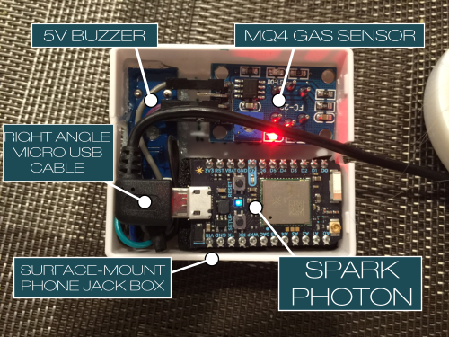
Stefan over at Hackster.io has written an article detailing his DIY Wi-Fi gas detector that sends SMS alerts:
Hey guys, back with another little project that I’ve been fiddling with for the past week. With kids around, every parent is thinking how to make their home safer for the little ones and for everybody in general. One of the most dangerous thing in the house can be the stove and since we have a gas-powered one, I always wondered why there are no simple gas detectors that can be used around the stove, just to alert instantly that gas may be leaking.DIY WiFi gas detector with text alerts – [Link]
Well, that was the moment when I decided to build one of my own. Having a Particle (Spark) Photon lying around, I decided to use that as a foundation for the project. I like the fact that they are very small and cheap, and also can be flashed over the Wi-Fi. Having that settled, I needed the gas sensor and some kind of alerting system.
The post DIY WiFi gas detector with text alerts appeared first on Electronics-Lab.
Oct 14, 2015
9-axis motion sensor and MCU reside in tiny package
9-axis motion sensor and MCU reside in tiny package:
by Susan Nordyk:
The post 9-axis motion sensor and MCU reside in tiny package appeared first on Electronics-Lab.
by Susan Nordyk:

Housed in a 5.2×3.8×1.1-mm package, Bosch Sensortec’s BMF055 9-aix sensor combines an accelerometer, gyroscope, and magnetometer with a 32-bit MCU to enable easy programming and customization. It can be used by designers creating advanced application-specific sensor fusion algorithms for robotics, gaming, remote controls, navigation systems, drones, and human interface devices for IoT projects.9-axis motion sensor and MCU reside in tiny package – [Link]
The BMF055 system-in-package integrates a triaxial 14-bit accelerometer, a triaxial 16-bit gyroscope with a range of ±2000 degrees per second, and a triaxial geomagnetic sensor. Based on a 32-bit ARM Cortex M0+ core running at up to 48 MHz, the Atmel SAM D20 microcontroller employed by the BMF055 provides in-system programmable flash memory and a rich set of peripherals and interfaces.
The post 9-axis motion sensor and MCU reside in tiny package appeared first on Electronics-Lab.
How to program the ATtiny85 with the Arduino UNO board
How to program the ATtiny85 with the Arduino UNO board:
by codebender_cc @ instructables.com:
The post How to program the ATtiny85 with the Arduino UNO board appeared first on Electronics-Lab.
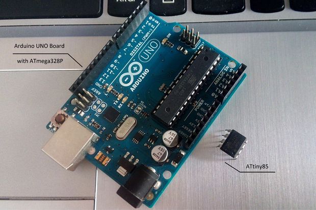
by codebender_cc @ instructables.com:
In this tutorial we will use an Arduino board as an ATtiny programmer.How to program the ATtiny85 with the Arduino UNO board – [Link]
To do this we will use one Arduino UNO board as an ISP (programmer) and one ATtiny85 micro-controller.
We will use Codebender – online Arduino IDE.
With the following procedure you will be able to program easily the ATtiny45 and ATtiny85 micro-controllers.
The post How to program the ATtiny85 with the Arduino UNO board appeared first on Electronics-Lab.
Unlock a Door with your Fingerprint
Unlock a Door with your Fingerprint:
by Kinoma @ instructables.com:
The post Unlock a Door with your Fingerprint appeared first on Electronics-Lab.
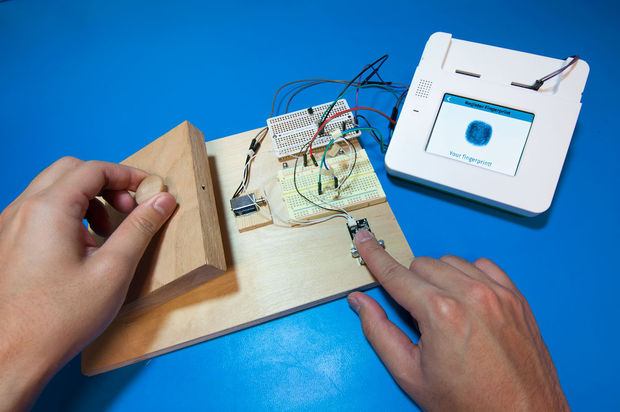
by Kinoma @ instructables.com:
We built a biometric fingerprint-controlled lock prototype. A fingerprint scanner is used to capture and store the fingerprints of authorized users. When the scanner recognizes a user, a solenoid plunger disengages and opens the lock.Unlock a Door with your Fingerprint – [Link]
The post Unlock a Door with your Fingerprint appeared first on Electronics-Lab.
Oct 13, 2015
Hacking a Blood Pressure Monitor
Hacking a Blood Pressure Monitor:
by Eduardo @ edusteinhorst.com:
The post Hacking a Blood Pressure Monitor appeared first on Electronics-Lab.

by Eduardo @ edusteinhorst.com:
I’ve been meaning to hack my blood pressure monitor for a while, and I finally got around to doing it! So, the idea is to mod a regular electronic blood pressure monitor to make it wireless and connected to the Internet, much like iHealth BP5 or Withings’. That makes detecting trends in your blood pressure much easier, since you can chart the data and even correlate it with other health data, such as how much sleep you’ve been getting, your weight or your level of activity. The model I have is the EW3106 from Panasonic. It’s quite old but from what I’ve seen the design hasn’t changed much throughout the years.Hacking a Blood Pressure Monitor – [Link]
The post Hacking a Blood Pressure Monitor appeared first on Electronics-Lab.
Hacked Apartment Intercom Barks at You or Buzzes You In
Hacked Apartment Intercom Barks at You or Buzzes You In:
Forgot your apartment keys? If you’ve got a ritzy building with a doorman, no problem. If your digs are a little more modest, you might only have an intercom panel that calls up to your apartment so someone can buzz you in. But if nobody is home, you’re out of luck. That’s why [Paweł] spent an hour whipping up an intercom connected automation system pack full of goodies.
 The design is pretty simple – an ATMega328P to snoop on the analog phone ringer in the apartment when the intercom call button is pushed, and a relay wired in parallel with the door switch to buzz him in. For added security, the microcontroller detects the pattern of button presses and prevents unwanted guests from accessing the lobby. Things got really fun when [Paweł] added a PCM audio module to play random audio clips through the intercom. As you can see in the video below, an incorrect code might result in a barking dog or a verbal put-down. But [Paweł] earns extra points for including the Super Mario Bros sound clip and for the mashup of the “Imperial March” with “The Girl from Ipanema”.
True, we’ve seen a slightly more polished but less [Mario] version of this project before, but the presentation of this particular hack has us grinning from ear to ear.
[Thanks, Haxor]
Filed under: home hacks, misc hacks

Forgot your apartment keys? If you’ve got a ritzy building with a doorman, no problem. If your digs are a little more modest, you might only have an intercom panel that calls up to your apartment so someone can buzz you in. But if nobody is home, you’re out of luck. That’s why [Paweł] spent an hour whipping up an intercom connected automation system pack full of goodies.
True, we’ve seen a slightly more polished but less [Mario] version of this project before, but the presentation of this particular hack has us grinning from ear to ear.
[Thanks, Haxor]
Filed under: home hacks, misc hacks
| Original enclosures: |
| screenshot-2015-10-07-at-10-21-30.png?w=150 |
| ad516503a11cd5ca435acc9bb6523536?s=96 |
| entryphone.jpg?w=400 |
Hacklet 79 – USB Projects
Hacklet 79 – USB Projects:
Universal Serial Bus was created to simplify interconnecting computers and peripherals. First released in 1996, hackers and makers were slow to accept this strange new protocol. Parallel and serial ports were simpler, worked great, and had decades of hacking with thousands of projects behind them. As the new standard caught on in the mainstream, RS-232 and parallel ports started disappearing. “Legacy free” PC’s became the norm. Hackers, Makers, and Engineers had no choice but to jump on the bandwagon, which they did with great gusto. Today everything has a USB port. From 8 bit microcontrollers to cell phones to children’s toys. This week’s Hacklet is about some of the best USB projects on Hackaday.io!
We start with [Michael Mogenson] and Two Component USB Temperature Data Logger, which may be the simplest USB device ever made. [Michael] isn’t kidding. This data logger consists of just a Microchip PIC16F1455 microcontroller and a USB connector. Microchip’s datasheet calls for a capacitor to smooth out power, but [Michael] made it work without the extra part. He used M-Stack by Signal 11 to implement the USB stack. Once connected to a PC, the PIC enumerates as a serial port device. It then sends its die temperature of the PIC once per second. It could do more, but that would probably require adding a few more components!
Next up is [davedarko] with USB cable tester. Dave recently spent some time installing USB RFID readers. These devices were only a few meters away from the computer controlling them. Even so, the power and USB data cables had to run through pipes and in some cases under water. It wasn’t fun troubleshooting a device to find that it was a shorted USB cable causing the problem. [Dave’s] solution is a tiny coin cell powered board that tests each of the 4 wires in a standard USB 2.0 cable. The board runs on an ATtiny45 microcontroller. [Dave’s] current iteration has footprints for mini and micro USB connectors, along with the standard USB-A.
[MobileWill] has a USB Tester of his own. This USB tester checks current consumption and rail voltage. It does this by connecting in-line with the device under test. It’s perfect for troubleshooting why your PC’s USB port goes into over-current protection every time you plug in your device. The tester is modular – you can use the base board with your own multimeter, or grab [Will’s] tester backpack and see the results right on the built-in OLED display. USB Tester is [Will’s] entry in the 2015 Hackaday Prize.
Finally, we have [ajlitt] with Tiny Bit Dingus (TBD). TBD is a USB interface to 6 wires. Think of it as a tiny version of the bus pirate. This lilliputian board holds a Freescale KL27Z ARM processor, which has more than enough power to handle things like I2C, SPI, PWM, or just about any other way to send data or wiggle wires. [Ajlitt] started this project as an excuse to learn KiCAD and gain some experience with surface mount solder stencils. The result is an absolutely tiny board that is all but lost in a USB socket. Programming is handled with the mbed library, though you can always use Freescale’s native tools. Flashing code on the TBD is easy with kut, a chrome browser plugin.
If you want to see more USB projects, check out our new USB projects list. Did I miss your project? Don’t be shy, just drop me a message on Hackaday.io. That’s it for this week’s Hacklet, As always, see you next week. Same hack time, same hack channel, bringing you the best of Hackaday.io!
Filed under: Hackaday Columns

Universal Serial Bus was created to simplify interconnecting computers and peripherals. First released in 1996, hackers and makers were slow to accept this strange new protocol. Parallel and serial ports were simpler, worked great, and had decades of hacking with thousands of projects behind them. As the new standard caught on in the mainstream, RS-232 and parallel ports started disappearing. “Legacy free” PC’s became the norm. Hackers, Makers, and Engineers had no choice but to jump on the bandwagon, which they did with great gusto. Today everything has a USB port. From 8 bit microcontrollers to cell phones to children’s toys. This week’s Hacklet is about some of the best USB projects on Hackaday.io!
We start with [Michael Mogenson] and Two Component USB Temperature Data Logger, which may be the simplest USB device ever made. [Michael] isn’t kidding. This data logger consists of just a Microchip PIC16F1455 microcontroller and a USB connector. Microchip’s datasheet calls for a capacitor to smooth out power, but [Michael] made it work without the extra part. He used M-Stack by Signal 11 to implement the USB stack. Once connected to a PC, the PIC enumerates as a serial port device. It then sends its die temperature of the PIC once per second. It could do more, but that would probably require adding a few more components!

Next up is [davedarko] with USB cable tester. Dave recently spent some time installing USB RFID readers. These devices were only a few meters away from the computer controlling them. Even so, the power and USB data cables had to run through pipes and in some cases under water. It wasn’t fun troubleshooting a device to find that it was a shorted USB cable causing the problem. [Dave’s] solution is a tiny coin cell powered board that tests each of the 4 wires in a standard USB 2.0 cable. The board runs on an ATtiny45 microcontroller. [Dave’s] current iteration has footprints for mini and micro USB connectors, along with the standard USB-A.

[MobileWill] has a USB Tester of his own. This USB tester checks current consumption and rail voltage. It does this by connecting in-line with the device under test. It’s perfect for troubleshooting why your PC’s USB port goes into over-current protection every time you plug in your device. The tester is modular – you can use the base board with your own multimeter, or grab [Will’s] tester backpack and see the results right on the built-in OLED display. USB Tester is [Will’s] entry in the 2015 Hackaday Prize.

Finally, we have [ajlitt] with Tiny Bit Dingus (TBD). TBD is a USB interface to 6 wires. Think of it as a tiny version of the bus pirate. This lilliputian board holds a Freescale KL27Z ARM processor, which has more than enough power to handle things like I2C, SPI, PWM, or just about any other way to send data or wiggle wires. [Ajlitt] started this project as an excuse to learn KiCAD and gain some experience with surface mount solder stencils. The result is an absolutely tiny board that is all but lost in a USB socket. Programming is handled with the mbed library, though you can always use Freescale’s native tools. Flashing code on the TBD is easy with kut, a chrome browser plugin.

If you want to see more USB projects, check out our new USB projects list. Did I miss your project? Don’t be shy, just drop me a message on Hackaday.io. That’s it for this week’s Hacklet, As always, see you next week. Same hack time, same hack channel, bringing you the best of Hackaday.io!
Filed under: Hackaday Columns
| Original enclosures: |
| hacklet-featured-image1.png?w=150 |
| ad516503a11cd5ca435acc9bb6523536?s=96 |
| twocomponent.png?w=400 |
| tester1.png |
| tester2.png?w=400 |
| tbd.png?w=400 |
Oct 8, 2015
ARDUINO sound activated flash or camera trigger
ARDUINO sound activated flash or camera trigger:
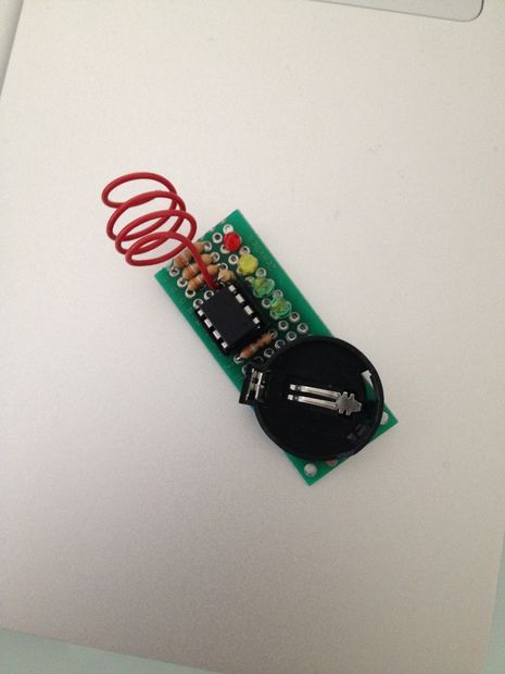
This instructable will show you how to build a simple circuit to connect to a ARDUINO micro controller that will detect sound and trigger your camera or flash for high speed photography. This is easy to assemble and only cost a few $$$ for the parts... Build the circuit.. The picture above is ...
By: Z-HUT
Continue Reading »
This instructable will show you how to build a simple circuit to connect to a ARDUINO micro controller that will detect sound and trigger your camera or flash for high speed photography. This is easy to assemble and only cost a few $$$ for the parts... Build the circuit.. The picture above is ...

By: Z-HUT
Continue Reading »
Programming an Arduino from Raspberry Pi
Programming an Arduino from Raspberry Pi:
Learn how to install the Arduino IDE on your Raspberry Pi so that you can write and upload programs onto an Arduino.Items needed:1x Raspberry Pi 1x ArduinoPlus what ever cables are needed such as USB to Arduino. Installs Assuming you have a Raspberry Pi setup(if not chick here ), we start from t...
By: nfarrow
Continue Reading »
Learn how to install the Arduino IDE on your Raspberry Pi so that you can write and upload programs onto an Arduino.Items needed:1x Raspberry Pi 1x ArduinoPlus what ever cables are needed such as USB to Arduino. Installs Assuming you have a Raspberry Pi setup(if not chick here ), we start from t...

By: nfarrow
Continue Reading »
Make This Cheap and Easy Mini Power Tool
Make This Cheap and Easy Mini Power Tool:
I showed a picture of my homemade mini power tool in one of my Instructables and mentioned how easy it was to make. I had also, immediately following, started this Instructable featuring it, but for some reason, it got side-tracked.Just yesterday I received a message from a member who saw that Instr...
By: tonep
Continue Reading »
I showed a picture of my homemade mini power tool in one of my Instructables and mentioned how easy it was to make. I had also, immediately following, started this Instructable featuring it, but for some reason, it got side-tracked.Just yesterday I received a message from a member who saw that Instr...

By: tonep
Continue Reading »
What can you do with a bad PC power unit
What can you do with a bad PC power unit:
Hi!This is my first instructable here on this site. I will show you how you can make simple connectors from the PSU of your old not working PSU.All the time I bought that type of connector and one day I sad it's time to thinking how to reuse old electronic equipment and see what can we do with.Let's...
By: Christian RobertA
Continue Reading »
Hi!This is my first instructable here on this site. I will show you how you can make simple connectors from the PSU of your old not working PSU.All the time I bought that type of connector and one day I sad it's time to thinking how to reuse old electronic equipment and see what can we do with.Let's...

By: Christian RobertA
Continue Reading »
Oct 7, 2015
Improve your drill press - by adding lights
Improve your drill press - by adding lights:
So I have my drill press for a while now and started to improve and refurbish it so it runs smoother, and is well maintained (... love good running tools). I thought its a good idea to make some instructables on my progress ... maybe someone is doing something similar and finds it useful.But let's s...
By: slurgXX
Continue Reading »
So I have my drill press for a while now and started to improve and refurbish it so it runs smoother, and is well maintained (... love good running tools). I thought its a good idea to make some instructables on my progress ... maybe someone is doing something similar and finds it useful.But let's s...

By: slurgXX
Continue Reading »
10 (of 100) Must-Learn Skills | Make:
10 (of 100) Must-Learn Skills | Make::

I love articles that detail must-learn skills that every adult should know. Popular Mechanics recently posted “100 Skills Everyone Should Know.” Here are ten of those skills that certainly every maker should know.
 First, determine which way the tree will fall. (If it looks like a tossup, call in a professional; perfectly vertical specimens require ropes to pull the tree in the desired direction.) At a comfortable waist level, make a horizontal cut on the side where the tree is going to fall, stopping about a third of the way through the tree. Then make a wedge cut down to the same line. The notch should open toward the direction of fall. Make sure you have a clear 45-degree rear escape route before starting the back cut, aimed slightly above the V of the notch. When the tree starts to move, quickly withdraw the saw and retreat to safety. Yelling Timmmberrr! is strictly optional.
 To confirm that the hitch is secure on the ball, lift the rear of the tow vehicle a couple of inches with the trailer tongue jack. Cross the breakaway chains under the tongue to prevent it from dragging on the pavement in case of a breakaway. To save yourself repeated trips to the rear of the trailer to check lights, turn on both the running lights and four-way flashers simultaneously.
 Before stepping on the ladder, check that it’s set at the correct angle, 75 to 78 degrees. Stand with the toes of your work boots against the ladder’s base and extend your arms horizontally. The ladder is at a safe angle when you can just grasp the rung at shoulder level with arms fully extended.
 One of the most elegant mechanical devices in the home, the sewing machine can be used on camping gear, light tarps, kites and myriad other manly stuff. To start, thread the bobbin and the machine. (Check your owner’s manual; machines have different threading procedures.) Once the needle is threaded and the bobbin thread pulled up from below, you’re ready to sew. Use the hand wheel on the right to raise the needle to its apex. Then lift the presser foot (the small slotted metal plate) and slide your two pieces of fabric underneath. Drop the needle down to just above the cloth, and lower the presser foot to hold the cloth in place. The two pieces of cloth should be pinned to hold them together. “Pin horizontally, perpendicular to the seam,” says wardrobe designer Marc Borders. “You break fewer needles.” Now hit the gas (gently) with the foot pedal. The needle will start bobbing up and down, and the feed dogs will pull the cloth under the needle. Press harder on the foot pedal to speed up the process. Keep one hand lightly on either side of the presser foot so you can guide the cloth along the desired line. Don’t push or pull the fabric, however. Let the feed dogs move it. To get the standard quarter-inch seam, keep the edge of the cloth even with the edge of the presser foot.
 Your old hard drive holds a treasure trove of info for would-be identity thieves. Simply deleting your files or reformatting the drive won’t truly blank the platters. “Formatting just kind of rearranges stuff on the hard drive,” says Art Costigan, an information security analyst with Global Network Security Consultants. “Anyone who knows anything about hard drives can unformat the drive and restore it to its previous condition.” Here are two surefire ways to zap your files for good. Charitable strategy: Purchase disk-cleaning software, such as Evidence Eliminator or cyberCide, that eliminates files by writing zeros over all the bits—yet still leaves the drive usable for others. That way, instead of clogging up landfills, you can help out those in need. The National Cristina Foundation donates old drives to schools and public agencies. Paranoid strategy: Nothing beats good, old-fashioned physical destruction. Government agencies use professional hard-drive shredders; you can approximate the effect with a 1/2-in. drill bit. Use a drill driver to puncture the platter in at least four places. Your hard drive will have taken its last spin. [Editor’s Note: One drilled hole is sufficient.]
Stick welding is one of the simplest and most inexpensive ways to get into welding,” Tocco says. (Some handymen prefer wire, or MIG, welding because it’s faster.) The first step in stick welding: Set the amperage for the electrode size and metal thickness. To strike the arc, brush the electrode against the workpiece as if striking a match. Hold the electrode at a 45-degree angle to the center of the joint and drag it along at a 15- to 20- degree lead angle, Tocco says. Maintaining a consistent arc of 1/8 in. or less, move the electrode slowly, so that the molten pool at the end of the electrode washes evenly into both pieces of metal.
 Fast and rough, these bits usually splinter the wood as they exit the hole. To make a cleaner hole, stop when the tip begins to break through the underside of the workpiece. Remove the bit, turn the workpiece over and place the tip in the exit hole. Complete the hole by boring in from the opposite side. TIP: Another way to avoid splintering: Clamp wood under the workpiece, then drill through it into the scrap.
 To make a vertical chopping cut (1), place the chisel at least 1/8 in. inside the cut line, with the bevel facing the waste side of the cut, and strike the tool firmly with a mallet. (You can use a hammer on chisels with metal end caps.) To remove the wood chip (2), hold the chisel with the bevel face down and take scooping cuts toward the vertical cut you just made. To finish the cut (3), pare vertically down to the line by holding the chisel like a dagger. TIP: Make several thin paring cuts rather than trying to remove the wood in one pass.
 It doesn’t respond well to pressure; use light strokes. On smooth, hard surfaces, mark the cut line with a carbide scriber (1) or file a starting notch. Use your thumbnail (2) as a guide to start. Apply cutting pressure only on the push stroke (3); lift the blade on the return stroke. Blades with 18 to 24 teeth per inch (tpi) are the most useful and versatile: Use 14 tpi for soft, thick metals (bar stock made of aluminum, copper or brass); 18 to 24 tpi for solid steel channel and pipe; 28 to 32 tpi for thin-wall armored electrical cable and sheetmetal.
 Always torque clean parts, either dry or lightly lubricated. (Adjust the torque spec down slightly for lubed parts.) When tightening multiple bolts, use a scattershot pattern; tightening in sequence can cause poor seating. HEADS UP: With a clicker-style wrench, stop at the first click—don’t give it a few extra degrees just to be sure.
See the original article on Popular Mechanics for the other ninety recommended skills. There are a lot of essential skills that didn’t make their list and some that don’t seem that essential. What did they miss?

I love articles that detail must-learn skills that every adult should know. Popular Mechanics recently posted “100 Skills Everyone Should Know.” Here are ten of those skills that certainly every maker should know.
Fell a Tree
Hitch a Trailer
Set Up a Ladder, Safely
Use a Sewing Machine
Secure Your Data
Stick Weld
Use a Spade Bit
Use a Chisel
Hack Sawing
Torque a Wrench
See the original article on Popular Mechanics for the other ninety recommended skills. There are a lot of essential skills that didn’t make their list and some that don’t seem that essential. What did they miss?
Gareth Branwyn
Gareth Branwyn is a freelancer writer and the former Editorial Director of Maker Media. He is the author or editor of over a dozen books on technology, DIY, and geek culture. He is currently a contributor for Boing Boing and WINK Books. And he has a new best-of writing collection and “lazy man’s memoir,” called Borg Like Me.Use Arduino and Relays to Control AC Lights and Appliances | Make:
Use Arduino and Relays to Control AC Lights and Appliances | Make::
 Photos: Christopher AldenIn building our latest project, The Great Houdini Escape Room, located in the Palace of Fine Arts in San Francisco, we tackled many Maker challenges. Everything in the room was built from “scratch.” The room uses over 5,000 feet of wire and is operated on over 5,000 lines of code running on 8 Arduino Megas. Those Megas connect to hundreds of inputs and outputs, including nearly 50 objects (such as lights) that are high voltage or, at least, require more voltage than the 5V that an Arduino can pump out.
Low voltage and high voltage environments are very different, and it can be challenging to build a complex system that requires both environments to work together seamlessly. And, of course, low-voltage systems are safe (think batteries) while high-voltage systems are dangerous (think wall sockets).
Since current can’t flow directly between low- and high-voltage networks, the interaction between these two systems is often managed via a relay. Data from an Arduino triggers a relay, which in turn switches a high-voltage connection on or off. Think of it as a light switch.
Wiring a relay, however, can be tricky. One side is low voltage and the other high. There needs to be a safe area for these relays to operate, away from tinkering hands. Arduino is fun because wires can be plugged in and moved at will — all without risk of electrocution. But once you bring high voltage into the mix, that easy plug-and-play ability goes away.
Wiring a relay is not a major undertaking, but we had to wire 50 of them. More significantly, however, we wanted to have the same flexibility with our higher-voltage elements as with our Arduino powered elements — it should be just as easy to swap out a lightbulb connection as an LED.
So we created the Plug & Play Arduino Relay. In brief, we put the relays in a junction box and mounted an electrical box on top with regular wall outlets inside. By wiring these outlets to the relays we created a plug-and-play device that works on both ends. Data wires come out of the box and can be safely connected to an Arduino. And any electrical device with a plug on the end — be it a light, a fan, or a blender — can be plugged and unplugged, as easily as you would with a simple power strip.
We built several of these reusable devices — there are eight used in the Great Houdini Escape Room — and now, any time we need to add, change, or remove a high-voltage device, there is no tricky high-voltage wiring needed – just plug and play.
Editor’s note: Alden’s Great Houdini Escape Room was profiled recently by Make: See our coverage here. Alden is interested in hearing more ideas for how he can improve on the design, either of the relay or upcoming escape rooms themselves. Visit him on the web at palace-games.com.
Low voltage and high voltage environments are very different, and it can be challenging to build a complex system that requires both environments to work together seamlessly. And, of course, low-voltage systems are safe (think batteries) while high-voltage systems are dangerous (think wall sockets).
Since current can’t flow directly between low- and high-voltage networks, the interaction between these two systems is often managed via a relay. Data from an Arduino triggers a relay, which in turn switches a high-voltage connection on or off. Think of it as a light switch.
Wiring a relay, however, can be tricky. One side is low voltage and the other high. There needs to be a safe area for these relays to operate, away from tinkering hands. Arduino is fun because wires can be plugged in and moved at will — all without risk of electrocution. But once you bring high voltage into the mix, that easy plug-and-play ability goes away.
Wiring a relay is not a major undertaking, but we had to wire 50 of them. More significantly, however, we wanted to have the same flexibility with our higher-voltage elements as with our Arduino powered elements — it should be just as easy to swap out a lightbulb connection as an LED.
So we created the Plug & Play Arduino Relay. In brief, we put the relays in a junction box and mounted an electrical box on top with regular wall outlets inside. By wiring these outlets to the relays we created a plug-and-play device that works on both ends. Data wires come out of the box and can be safely connected to an Arduino. And any electrical device with a plug on the end — be it a light, a fan, or a blender — can be plugged and unplugged, as easily as you would with a simple power strip.
We built several of these reusable devices — there are eight used in the Great Houdini Escape Room — and now, any time we need to add, change, or remove a high-voltage device, there is no tricky high-voltage wiring needed – just plug and play.

WARNING:
This project involves wiring for high-voltage applications. Use caution whenever dealing with high-voltage wiring, including following directions carefully and general safety practices. Safe assembly and operation of this project is the user’s responsibility. Do not make changes to the system while the device is plugged in.Editor’s note: Alden’s Great Houdini Escape Room was profiled recently by Make: See our coverage here. Alden is interested in hearing more ideas for how he can improve on the design, either of the relay or upcoming escape rooms themselves. Visit him on the web at palace-games.com.
Maximizing a Solar Panel
Maximizing a Solar Panel:
Solar panels seem like simple devices: light in and electricity out, right? If you don’t care about efficiency, it might be that simple, but generally you do care about efficiency. If you are, say, charging a battery, you’d like to get every watt out of the panel. The problem is that the battery may not draw all the available current, basically leaving capacity on the table.
The solution is a technique called MPPT (Maximum Power Point Tracking). Despite sounding like a Microsoft presentation add on, MPPT uses a DC to DC converter to present a maximum load to the solar cell while providing the desired current and voltage to the load. MPPT is what [Abid Jamal] implemented to manage his solar charger.
In addition to the solar panel and DC to DC converter, [Abid’s] project uses an Arduino, an LCD, some indicator LEDs, and some discrete components. He even included an ESP8266 to provide wireless data logging. The finished project resides on perf board and lives in an acrylic case.
There’s a similar MPPT project in the Hackaday prize competition (in fact, the video below is from the creator of that project), and we’ve seen other MPPT builds, too. It might be interesting to contrast the different designs.
FPGA CNC
FPGA CNC:
When you think of a CNC controller you probably think of a PC with a parallel port or some microcontroller-based solution like a Smoothie Board. [Mhouse1] has a different idea: use FPGAs as CNC controllers.
FPGAs inherently handle things in parallel, so processing G code, computing curves and accelerations, and driving multiple stepper motors at one time would not be an issue at all for an FPGA. Most computer-based designs will have slight delays when trying to drive everything at once and this introduces some mechanical jitter. Even worse jitter occurs when you have an old PC trying to run everything when some other task takes over the CPU.
In all fairness, [Mhouse1’s] design does include an Altera CPU on the FPGA to handle some tasks that CPUs are good at, but the FPGA allows the design to create I/O devices specifically for the task at hand. The CPU is also running an RTOS (MicroC OS II) and a Python GUI that runs on a controlling PC.
There’s an older article about using an FPGA to control a CNC machine that has a lot of good information about designing such a beast, if you are interested. However, that design is a lot less ambitious than this one. [Mhouse1] wants the controller to be machine agnostic, and he’s demonstrated it on a cheap DVD-based laser cutter as well as a modified Shapeoko machine.
If you want an introduction to FPGAs, you might want to get started with our tutorial on cheap FPGA development. Or, you can learn a lot with just your Web browser.
Smart Phone Camera Turns Laser Cutter into Hi-Res Scanner
Smart Phone Camera Turns Laser Cutter into Hi-Res Scanner:
Getting decent macro photos always seems to be a chore. Some important detail always seems to be just outside of the depth of field, or you have to be zoomed in so close that you get great detail in one spot but miss the big picture. [Nate B] had such a problem while trying to document some PC boards, and he came up with a nifty hack that uses a laser cutter and a smart phone camera to do the job.
Click for detail.
Having first tried scanning the boards with a flat-bed scanner but finding the depth of field unsatisfactory, [Nate B] then went on to his Samsung phone’s camera. Set to panorama mode, he manually scanned across the boards and let the camera stitch the images together. The results were better, but the wobblies got the better of him and the images showed it. He then decided to use a laser cutter — with the laser disabled, of course — as an impromptu X-Y stage to raster his camera above the boards. In a slightly cringe-worthy move, he gingerly clamped the phone to the cutter gantry, started the panorama, and let the cutter move over the board. This results in a rock-solid pictures of his boards with a lot of detail – perfect for his documentation. As a bonus, the honeycomb laser cutter bed makes for an interesting background texture.
Obviously anything could be used to raster a camera and achieve similar results, but full points here for maximizing available resources and not over-complicating a simple job. Yet another reason you can use to justify that laser-cutter purchase.
Getting decent macro photos always seems to be a chore. Some important detail always seems to be just outside of the depth of field, or you have to be zoomed in so close that you get great detail in one spot but miss the big picture. [Nate B] had such a problem while trying to document some PC boards, and he came up with a nifty hack that uses a laser cutter and a smart phone camera to do the job.
Click for detail.

Having first tried scanning the boards with a flat-bed scanner but finding the depth of field unsatisfactory, [Nate B] then went on to his Samsung phone’s camera. Set to panorama mode, he manually scanned across the boards and let the camera stitch the images together. The results were better, but the wobblies got the better of him and the images showed it. He then decided to use a laser cutter — with the laser disabled, of course — as an impromptu X-Y stage to raster his camera above the boards. In a slightly cringe-worthy move, he gingerly clamped the phone to the cutter gantry, started the panorama, and let the cutter move over the board. This results in a rock-solid pictures of his boards with a lot of detail – perfect for his documentation. As a bonus, the honeycomb laser cutter bed makes for an interesting background texture.
Obviously anything could be used to raster a camera and achieve similar results, but full points here for maximizing available resources and not over-complicating a simple job. Yet another reason you can use to justify that laser-cutter purchase.

Subscribe to:
Comments (Atom)